LIMENET / OCEAN ALKALINITY ENHANCEMENT

A new horizon for ocean alkalinity.

Two vessels. A shared course.
A new way to distribute alkalinity at sea.

Explore the concept
From the full system to the water beneath it.Future concept · Illustrative rendering

01 / THE IDEA

Work with the ocean’s
natural carbon chemistry.

Adding alkalinity can increase seawater’s capacity to take up CO₂ from the atmosphere.

Limenet is exploring how to deliver that alkalinity across a broad area of the ocean. In this future concept, a bulk carrier and a support vessel travel together, towing a floating distribution line fitted with submerged outlets.

The idea combines controlled delivery, movement through fresh seawater and environmental monitoring. The aim is to enable durable carbon removal, with performance and environmental effects to be demonstrated through research and validation.

The images on this page are concept renderings from Limenet’s storyboard. They illustrate a proposed system, rather than a full-scale installation already operating at sea.

THE SYSTEM, AT A GLANCE

One coordinated operation.

Each part has a different job.
Together, they create a moving delivery system.

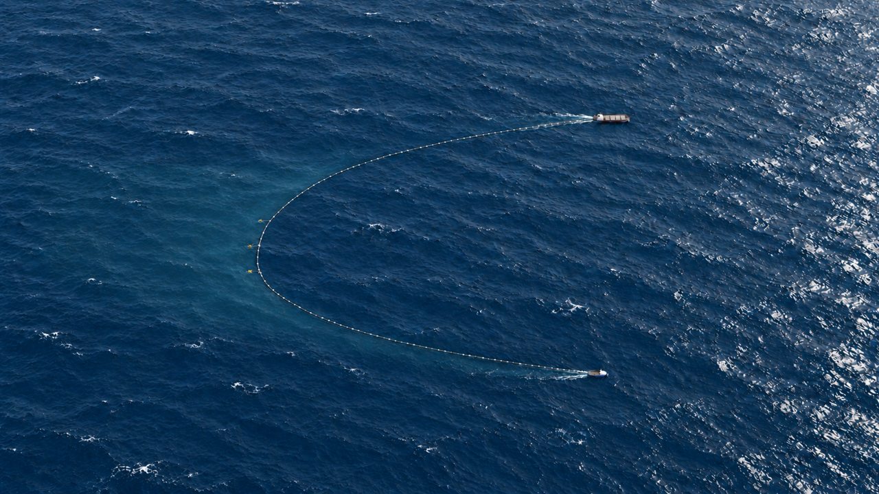
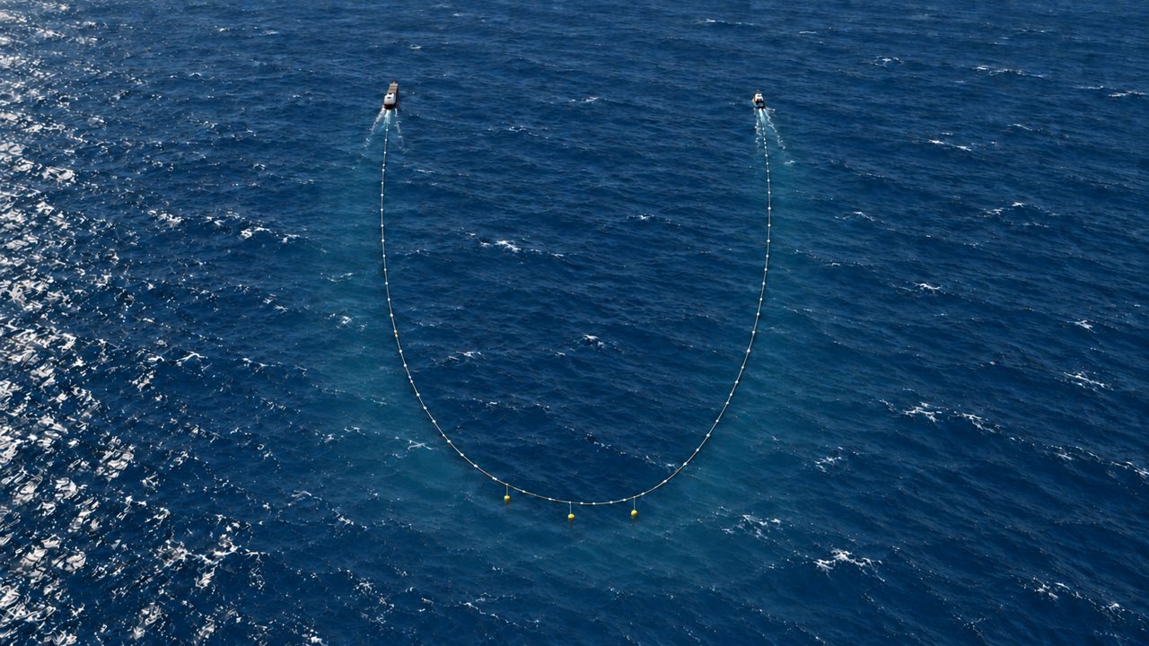
High aerial concept view showing the two separated vessels connected at their sterns by a long, curved floating hose.AERIAL VIEW / SYSTEM GEOMETRY
1

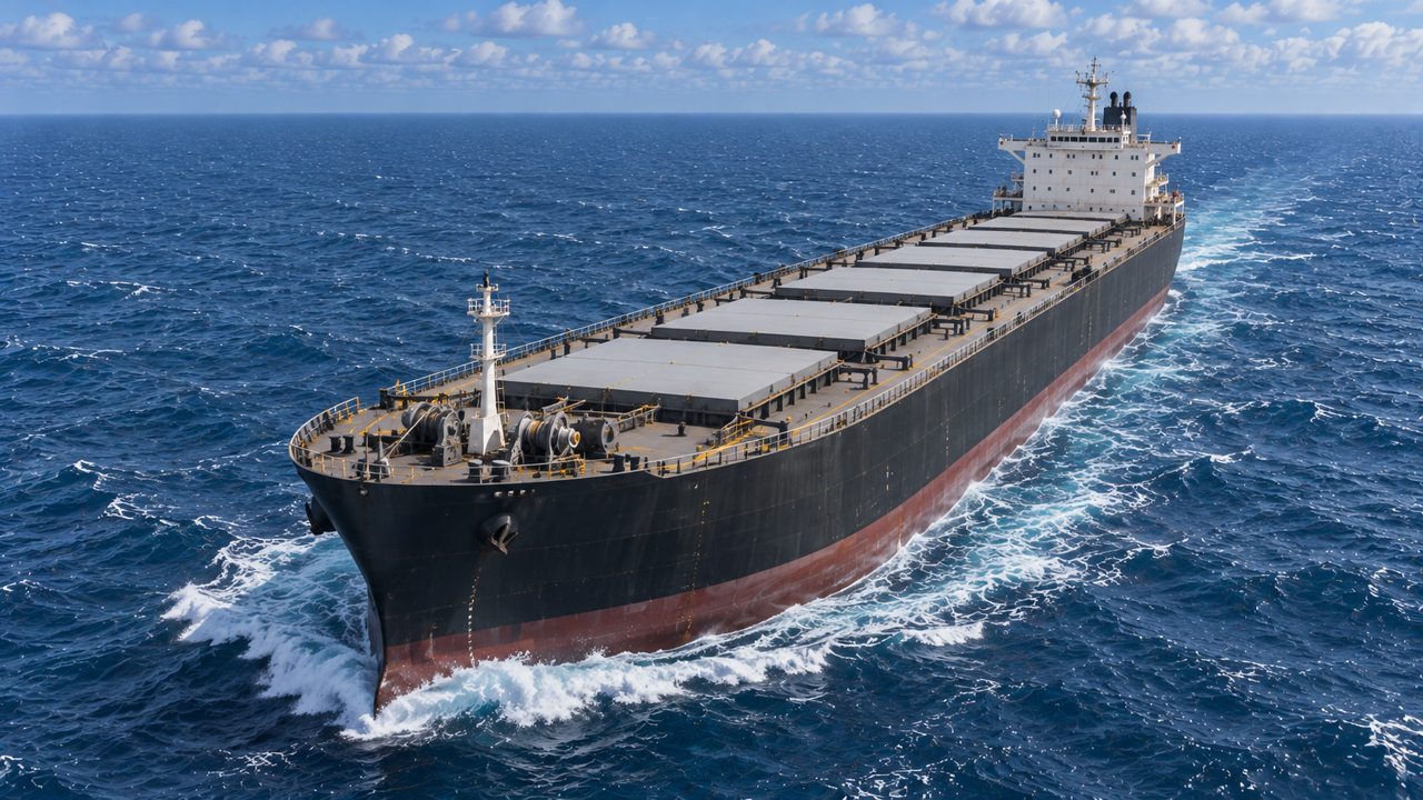
Bulk carrier

Carries the alkaline material in enclosed holds and supplies the distribution system.

2

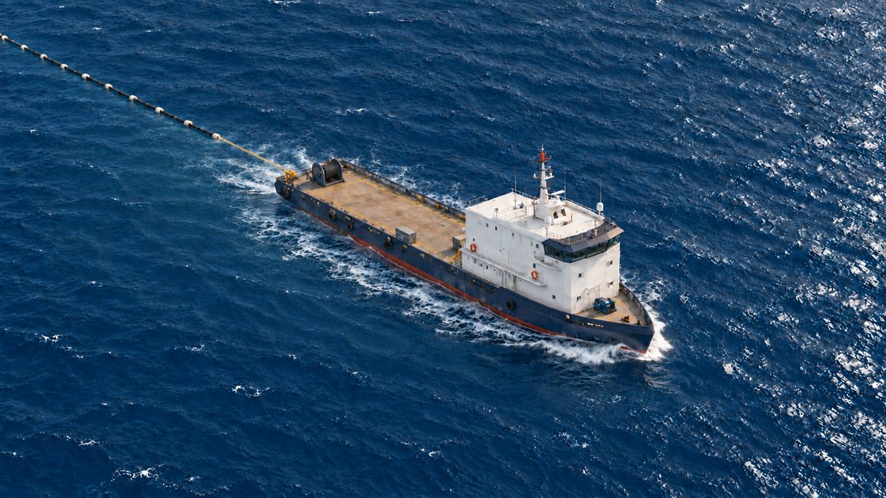
Support vessel

Maintains the other end of the line while coordinating course, separation and towing.

3

Floating distribution line

Connects the sterns in a broad trailing curve and carries the delivery modules.

130 mBulk carrier length
65 mSupport vessel length
1,000 mBetween stern attachment points
3,000 mDistribution line length

Indicative dimensions from the concept storyboard. Renderings are not to scale; final geometry requires naval and engineering validation.

02 / FROM SHIP TO SEAWATER

Carry it. Deliver it. Keep moving.

Follow the material from the vessel
to the submerged outlets.

Front-quarter view of the concept bulk carrier with its cargo hatch covers closed.
01 / CARRY

Material on board

The carrier provides storage for the alkaline material used during the operation.

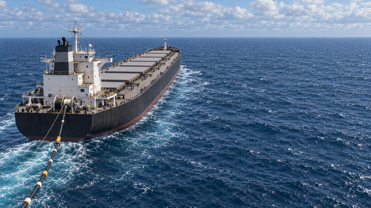
Stern of the concept merchant vessel, showing deck equipment and the floating hose connection trailing behind the ship.
02 / SUPPLY

A connection at the stern

The distribution line is supplied from the vessel and follows behind it as the system advances.

Support vessel with an open working deck and a floating line trailing from its stern.
03 / COORDINATE

Control the other end

The support vessel helps maintain the line’s spread as both ships move on coordinated courses.

04 / RELEASE BELOW THE SURFACE

A small-scale view
of a wide-area idea.

Submerged horizontal outlets introduce the alkaline liquid into the surrounding seawater at multiple points along the line.

Close to each outlet, the jet mixes with seawater. As the vessels move forward, the released material is carried aft relative to the system and diluted by turbulence and currents.

The outlets deliver alkalinity.
Atmospheric CO₂ enters through the sea surface over time.
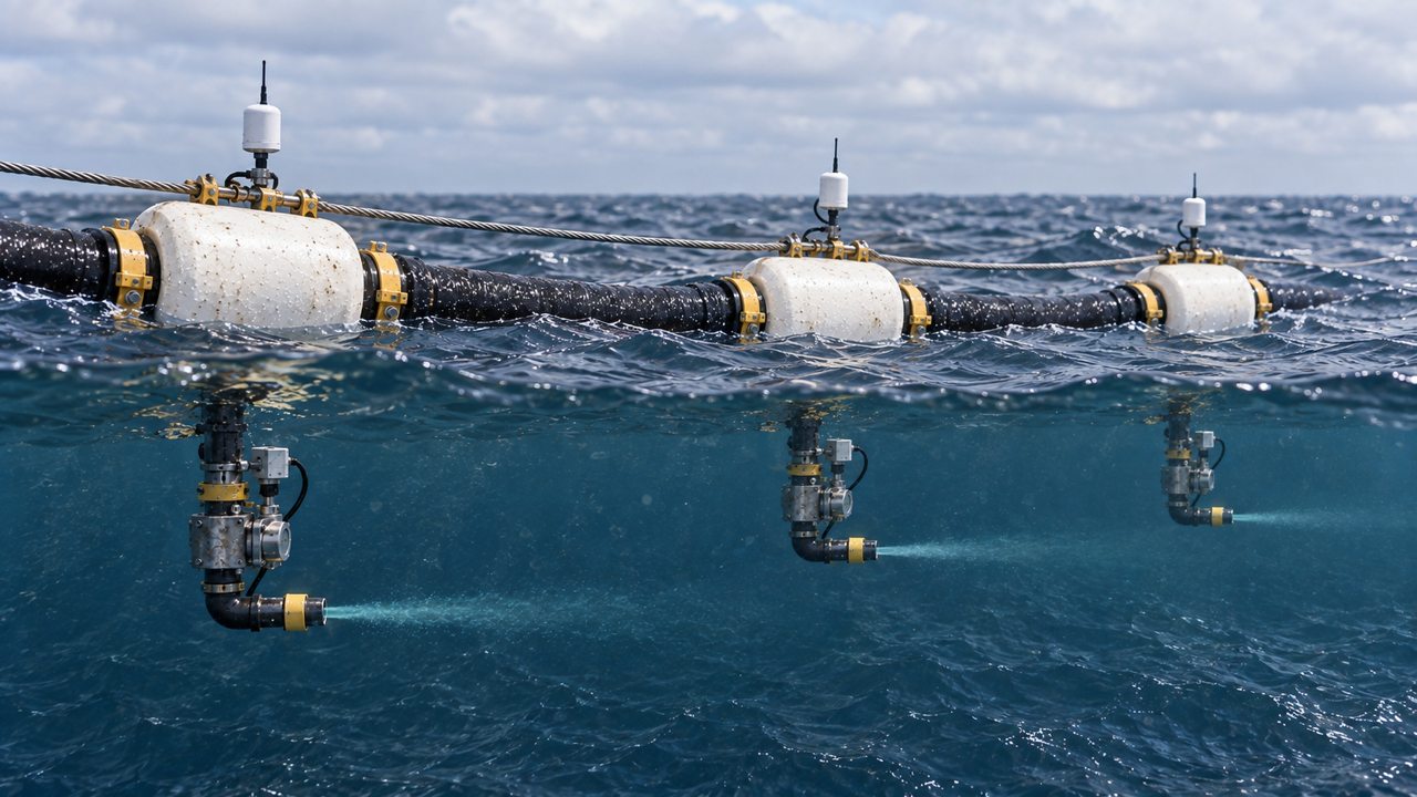
Split-level concept rendering of three floating modules with vertical feeds and horizontal submerged outlets releasing liquid into seawater.
Floating modules above; horizontal outlets below. The visible wisps illustrate release and mixing.

03 / MOVEMENT AND MIXING

Ships move forward.
Treated water stays behind.

The initial jet and the larger treated-water
footprint are two different scales of motion.

TOP VIEW / SHIP-FIXED FRAME

Direction of travel

Forward vessel motion and a treated-water footprint behind the distribution lineThe bulk carrier and support vessel advance upward. The hose joins their sterns and curves behind them. Dots released along the hose move downward, aft relative to the vessels. This is a qualitative explanation, not a hydrodynamic model.Direction of travelBulk carrierSupport vesselFloating lineMultiple release pointsMixing and dilution aftRelative to the advancing vessels
  1. 1 Bulk carrier
  2. 2 Support vessel
  3. 3 Floating line with multiple release points

Mixing continues behind the vessels.

Qualitative schematic. Particle speed, colour and spacing do not represent measured flow or concentration.

01

Release along the line

Alkalinity is introduced at distributed outlets, rather than from a single discharge point.

02

Move into fresh seawater

Both vessels maintain a coordinated heading. In their frame of reference, the released water moves backwards relative to the ships and hose.

03

Let the footprint develop

The treated-water footprint extends downstream of the release points along both arms and the trailing section. Currents, waves and turbulence shape how it spreads.

The line is a delivery system, not a barrier enclosing the sea. Actual dispersion depends on operating conditions and local ocean dynamics.

Aerial concept view of the vessels advancing to the right, with the floating hose and a faint, broad treated-water area extending behind them to the left.
A broad, gradually diluting footprint. The subtle tint helps identify the treated water; it is not a concentration map or a prediction of visible ocean colour.

04 / THE CARBON CONNECTION

Alkalinity creates capacity.
The atmosphere supplies the CO₂.

Alkalinity is seawater’s acid-neutralising capacity. Increasing it changes the balance of dissolved carbon and can create conditions for additional atmospheric CO₂ uptake.

01

Increase alkalinity

Adding an alkaline substance changes seawater chemistry and initially raises local pH.

02

Enable atmospheric uptake

Lower dissolved CO₂ can drive transfer from the air into the ocean. The rate depends on gas exchange, mixing and circulation.

03

Retain dissolved carbon

The additional carbon is held in dissolved bicarbonate and carbonate forms, within the ocean’s natural carbon chemistry.

This process takes time. The moment of release is not the moment when all associated atmospheric CO₂ has been removed.

Net removal must be verified. Uptake estimates must account for material production, energy use, vessel operations and other lifecycle emissions.

05 / OBSERVE, UNDERSTAND, ADJUST

Monitoring is part of the system.

From measurements in the water
to evidence of carbon removal.

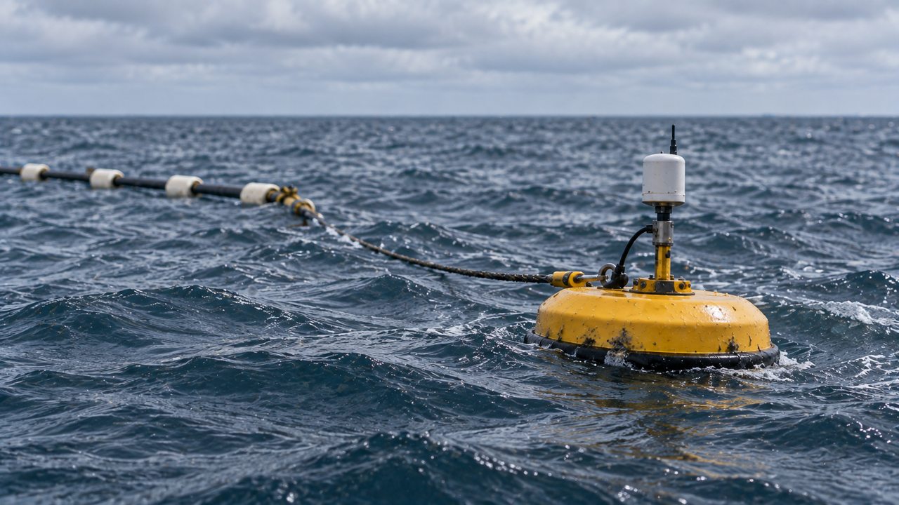
Concept yellow monitoring buoy with a mast and antenna riding the waves near the floating line.
ABOVE THE SURFACE

A platform for observation

The buoy illustrates how monitoring equipment can accompany the operation.

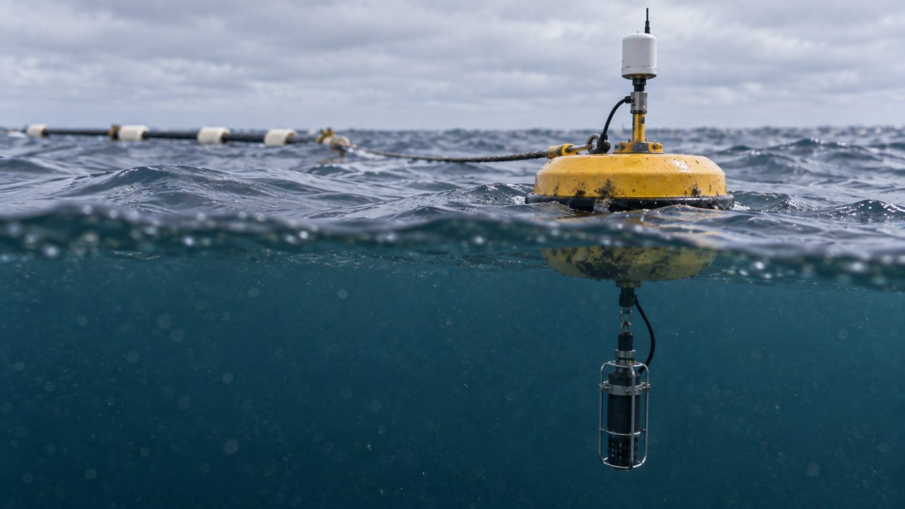
Split-level concept view of a yellow buoy and its attached submerged sensor probe.
BELOW THE SURFACE

Measurements where mixing happens

Submerged instruments and water sampling help characterise conditions in and around the treated water.

01 / BASELINE

Know the receiving water

Establish background chemistry and ecological conditions before delivery, with reference measurements outside the treated area.

02 / OPERATION

Track the response

Combine observations of pH, carbonate chemistry and physical conditions with checks for precipitation and environmental effects. Dosing and dilution must keep changes within site-specific operating limits.

03 / VERIFICATION

Connect measurements and models

Use validated models, field observations and lifecycle accounting to estimate additional CO₂ removal and report uncertainty.

A buoy alone cannot verify carbon removal. Instrument selection, sampling design, operating limits and responses to unexpected conditions are part of the research and validation programme.

THE PATH AHEAD

A concept to develop.
A process to validate.

This page presents Limenet’s vision for future ocean alkalinity delivery. The engineering, material formulation, operating envelope and environmental response require further development and testing.

Progress towards deployment depends on evidence: reliable mixing, retained alkalinity, assessed ecological effects, robust carbon accounting and the relevant permissions.

Back to the full picture

READ FURTHER

Visual concept and indicative geometry: Limenet storyboard, 14 September 2026. Scientific principles: OAE Best Practices Guide, carbonate chemistry and MRV chapters. The proposed vessel system is presented as future development.